
Model-In Special
Application of PIC Microcontroller to Model Trains
I commenced a new feature in my model railway hobby last year. This is programming of a microcontroller called 'PIC' (Peripheral Interface Controller) to be applicable to model trains. The PIC is one type of 8-bit microprocessor which is very popular among both industrial developers and hobbyists worldwide, being provided by Microchip Technology Inc., an American company. Its range varies from tiny 6-pin chips to 144-pin large chips. The type of the PIC which I have particularly got interested in is an 8-pin type series packaged in a dual in-line module, which allows easy installation in terms of both hardware and software. Because of its tiny configuration, the size of memory space is very small, such as 1K to 2K words programme memory (or flash memory) and 64 to 128 bytes data memory (or RAM; Random Access Memory). However, it runs reasonably fast due to 4 MHz to 20 MHz internally oscillated clock (pre-programmable), and along with a variety of peripheral interface functionality, it allows implementing a small-scale automated system adequate for small operations including a model train.
The following sections introduce some PIC applied systems which I developed for Gauge 1 live steam and O scale model trains.
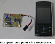
The device is constructed in a small universal printed circuit board, called a ‘breadboard’ with dimensions of 30 mm x 40 mm, and can reproduce recorded sounds, such as a locomotive whistle, an EMU’s horn, EMU’s traction noises, etc., being triggered by a radio controlled command (R/C).
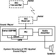
As a system, the device consists of three tiny IC chips, namely a PIC microcontroller, a serial EEPROM (Electrically Erasable Programmable Read Only Memory) as an external memory, and an audio amplifier module, all of which are packaged in an 8-pin dual in-line chip. With this configuration, the system can effectively playback recorded sounds based on the data memorized in the serial EEPROM.
The key factor in achieving this tiny sound system is the serial EEPROM. Usually, the sound source is located in an external memory because of its larger size of data, the reason for which is mentioned in the next paragraph. The interface between the processor and external memory requires multiple lines, e.g. 24 lines containing a 16-bit address bus and 8-bit data bus, even in a small-scale microprocessor system. In contrast, the serial EEPROM can be connected to the PIC through only two lines, namely clock and data, which can greatly simplify the structure of the target device, although intensive software logic is required to handle communication between the PIC and memory, data reading and writing, on a bit data stream basis. Actually, I was struck with this simplicity and intrigued to develop the sound device by myself.
The sound source is based on the PCM (Pulse-code Modulation) method, which is a common form of digital audio technology in computers, compact discs, telephone and other digital audio applications. In a PCM data stream, the amplitude of the analog signal of the sound is sampled at a pre-determined frequency, and each sample is quantized (or digitized) as data in a certain bit length. My system uses data of an 8 kHz sampling rate with 8-bit data range. This resolution is rather rough compared to genuine audio application systems, such as 44.1 kHz with 16-bit stereo, but it is enough to perform in the hobby area. I once learned that even in the real world, the 8-kHz with 8-bit PCM is a common arrangement for telephone exchanging networks.

Now, let’s consider how much volume of data is required for replaying a locomotive whistle sound. 8-kHz/8-bit means that 8-Kbyte of data is necessary for one second of sound. For example, to playback a locomotive whistle for four seconds, 4 x 8000 = 32000 bytes (32 Kbytes) data capacity is required for the memory. This data size is relatively large compared to the internal memory of the PIC, and this is why an external memory is essential in the sound player device. My system applies a 64 Kbyte serial EEPROM, allowing it to accommodate two types of 4-second sound for reproduction.
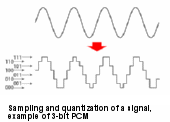
In the system, the PIC reproduces the sounds by reading out a stream of PCM data at 8 kHz timing, every 1/8000 seconds, and powers the speaker through the audio amplifier based on the amplitude defined by the PCM data, performing digital to analog conversion. Here, another key factor is how to convert the digital data to analog signals. The applied methodology is PWM (Pulse-width Modulation) output, which can also greatly simplify the structure of the output. In this method, the PIC switches on and off the output at a timing rate determined by each piece of PCM data. Then, the average value of the output voltage (and current) to be fed to the speaker varies according to the duty rate of each cycle of the pulses created by the PIC’s switching. The longer the switch is on compared to the off periods, the higher the total power supplied to the speaker. The main advantage of the PWM is that power loss in the switching devices is very low.
In the PIC, the PWM functionality is integrated as built-in hardware, and this is helpful for the software to conduct this type of analog conversion. Note that the PWM method is very common everywhere in the real world for speed control of motors for trains, automobiles, home electric appliances, lighting, etc.
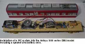
My latest application of this system is to a Keihin Kyuko 1000 series model train, which I built from scratch about 5 years ago. The model train can playback Siemens traction noises that sound as if they sing a melody, a stream of scales, ♫ D,C,E,F -----. The playback is in two modes, one is just playing a pre-programmed melody and the other reproducing recorded sounds, which are interchangeable by detecting a magnet marker located on the track by means of the sensor. When it hits the marker, it also produces the horn sound of an EMU as well as changing the sound playback mode.
Motor Speed Controller
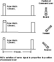
Again, the system uses the PWM method to vary the speed of motors responding to a remote control command through R/C. The remote control command from the R/C receiver is a servo signal which is a stream of pulses, which transitions at approximately a 17 milliseconds interval. The width of the pulses varies in proportion to the position of the control lever on the R/C transmitter. The variation of the width of pulses is only about 0.6 milliseconds at full range, forward-most to reverse-most via neutral. Counting these variations with reasonable resolution is a little bit tough for the software to process. However, thanks to a built-in timer in the PIC, this processing could be accomplished without imposing an excessive load on the software.
I applied this system to a scale model of the EF53 electric in O scale as a battery powered locomotive. Due to space constraints for installation on the locomotive, the device was installed on an attached passenger carriage, which feeds the motor power to the locomotive. Also implemented together was a sound player which emits the electric locomotive’s whistle sound, responding to a command through R/C.
Advantage: Low Cost Integration
The great advantage of the PIC application is its low cost integration. A tiny 8-pin chip of the PIC family costs in the range of from 50 Yen to 150 Yen. A chip of the 512 Kbit (64 Kbyte) serial EEPROM costs 150 Yen. A chip of the audio amplifier costs 60 Yen. Other required miscellaneous passive parts, such as register, capacitor, transistor and a breadboard can be purchased at a much lower cost than active electronic parts such as the PIC and memory. Thus, a control device packaged in a breadboard for the aforementioned applications is created within a total cost lower than 500 Yen. All of the parts are available through on-line shops, and they can be easily purchased through Internet shopping.
On the other hand, this is kind of a microprocessor system, and software development, or programming, is necessary in a specific development environment. However, Microchip provides a license-free IDE (Integrated Development Environment) package called MPLAB, in which an assembler, linker, software simulator and debugger are contained. You can download this software package free of charge from the Microchip web site and easily create the software development system for PICs in your PC. A high-level language, 'C' is also usable in the environment by separately downloading that complier. Another required tool is a PIC programmer, which is dedicated to loading the object codes generated in the form of so called ‘Hex file’ by the MPLAB IDE into the flash memory in a chip of the PIC, through the USB port connection. The cost of the programmer is a little bit higher, around 4,000 Yen, though.
Conclusion
I use an assembler for programming. I prefer a more primitive way compared to high-level language in programming for this type of tiny processor system. It is like driving a car by means of manual transmission rather than by using automatic transmission. The number of instructions for assembler programming is only 35 for a regular member of the PIC family, which is not very difficult to learn. Some people hate the PIC and use other types of microcontrollers, claiming that the architecture of the PIC is not straightforward, rather crooked. I understand this viewpoint. However, this is just a question of proficiency, and you would be able to get the hang of the instructions soon after experiencing development of some systems. You do not need to develop everything from scratch, but there is a lot of information on the PIC programing available on the Internet, along with an extensive collection of application notes, including source code lists for some common functions using either assembler or C language. You can utilize these programs as either a template or use them as they are for your application.
Since so many peripheral functions are packaged in a tiny chip, a lot of initial setting is required to optimize the functionality of your system. Because of this drawback, along with the narrower memory space, the programming is likely to be tricky. I sometimes fell into a pitfall when developing a program, and needed one day to three days until finding out the reason for the problem and thus ironing out the application.
Another effort required is arranging a sound source. This is achieved through the following process:
Download MP4 formatted digital video and audio data of your favourite movie from the You Tube site.
From the data, take out only the audio data in the MP3 format.
Convert it into 8-kHz/8-bit monaural PCM data in the WAV format common in the Windows environment and cut the desired portion from the sounds, adjusting the amplitude and length as well.
Modify the data by means of a binary editor, deleting unnecessary header in the data and adding an index specific to your design of PIC system.
Load the binary data into a serial EEPROM by using a PIC programmer in the MPLAB IDE.
All the procedures above can be done by using on-line format converters and/or license-free software tools obtainable free of charge through the Internet.
Software Development
You may say what is the benefit of developing such a system for your model trains by yourself? There are some types of commercialized electronic products for model trains, such as DCC (Digital Command Control) and the Quantum system, with much more functionality that includes not only a sound player but also various types of controls. Even toy trains, including Takara Tomy's Plarail models, are fitted with more intensive sound functionality. The reason is just pleasure (or complacency) in creating something from scratch by yourself. It is probably advantageous for elderly people like me in preventing dementia, as I need to exercise my brain intensively when working on programing and debugging.
I demonstrate my PIC applied systems at operation meetings sometimes, and they have caught the attention of other modellers.